The LEDs are connected to the power supply (from the previous post). I needed some way to turn them on and off when the Arduino gave the command, so I used a transistor as a switch. I made a bit of a mistake when ordering the transistors. I didn’t check their size.
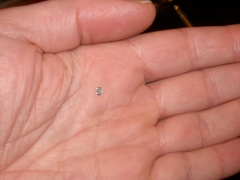
When they arrived it took me a while to realise that this little plastic strip had a backing you peel off and then these tiny transistors fall out. Well, waste not want not and all that. There must be some way to use them.
These are designed for surface mounting, i.e. you create three small pads of copper with solder on top, add flux, place the transistor on the pads and apply (very) hot air until the solder melts, joining transistor and board. It’s called “reflow soldering”, and it’s a good way to build things commercially, but I would have to buy the heater and have the boards specially made.
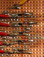
So, what I actually did was to solder two parallel pieces of wire on adjacent tracks of some Veroboard (going across the existing gap in the tracks). Then I cut a small piece out of one wire where the gap was (using a small knife). I placed the transistor so that one wire was on the uncut side and two wires were on the cut side, either side of the cut. Then, holding the transistor in place with a tiny screwdriver pressed down from above, I heated the three pieces of wire one at a time until the solder round them briefly melted.
It wasn’t as easy as it sounds; the transistor would move whenever I looked at it, the soldering iron tip was too big for the task, and I did it with the soldering iron in one hand (a 25 Watt Antex I bought when I was 16), magnifying glass in the other, and solder carefully positioned. Nonetheless, to my surprise, they all worked afterwards.
 These are BSS316N MOSFETs (Metal Oxide Silicon Field Effect Transistors). They work differently to ordinary transistors. Instead of amplifying a current, they are switched on by applying an electric field. The advantages are that, apart from during switching, they need almost no current to keep them switched on or off, and the input used to control them is electrically isolated from the current being switched. The only disadvantage is that they are easily damaged by static electricity, which means remembering to touch some earthed metal before handling them – every time.
There’s three wires:
* “drain” connects to the LEDs
* “source” connects to negative
* “gate” is the controlling input and connects to the arduino
This is the circuit (I made up a symbol for the MOSFET because I’m lazy):
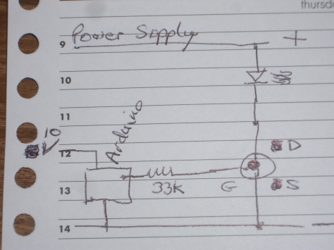
Since the switching input (the “gate”) is electrically isolated from the main current (that flows from the “source” to the “drain” (electrons from from negative to positive)), it’s tempting to connect the gate directly to the output of the arduino. However, when the arduino output changes from low to high, the gate acts like a capacitor and takes a large current for a very short time while it “charges”. It’s a very short time, but it’s a lot more than the 20 mA maximum the arduino is rated at. So I adding a resistor between the arduino output and the gate, just to be sure.
Ideally you should switch MOSFETs as quickly as possible (i.e. allow as much current to flow through the gate you can). With 5 Volts from the arduino, the minimum resistance to limit the current to 20 mA is (5 / 0.02) = 250 Ohms. However, I happened to have a hundred 33K resistors, so I used them 🙂 It does mean that switching will take longer, and the transistors will get warmer, but the amount of energy needed to create the electric field really is very, very small, so I guessed that I would get away with it. I measured the temperature rise; with a MOSFET switching on and off 200 times a second there’s a temperature rise of one degree Centigrade. Quite possibly thats one degree more than if I had used 250 Ohms.
So here they are:

2 thoughts on ““Space and Time” 3: Switches”